2022-11-01
 Note: A water jacket heater is recommended for stand-by generator set applications installed in a cold climate.
Preheater
The glow plug system supplies heat to the cylinders so that compression temperatures are sufficient to ignite the fuel.
To aid in starting the engine when the temperature is 50°F[10.0°C]or below an intake air preheater is available.
Preheater equipment consists of a hand-priming pump to pump fuel into the intake manifold and a switch to turn on the glow plug which is electrically heated by the battery. Fuel burns in the intake manifold and heats the intake air.
Warning: Do not use vapor in conjunction with the preheater. To do so could result in a fire.
Warning: Do not use vapor in conjunction with the preheater. To do so could result in a fire.
To use the preheater for cold starting
- Set the throttle in idle position.Turn the glowplug toggle switch to the “ON” position. The red indicator light must be on.
- After the red light has been on for 20 seconds,start cranking theengine. As soon as the engine begins rotating, operate the preheater priming pump to maintain 80 to 100 psi [552 to 693 kPa] fuel pressure. Use of the primer before the 20- second interval will wet the glow plug and pre vent heating.
- If the engine does not start within 30 secondsstop cranking. Wait one or two minutes and repeat the cranking operation.
- Afterthe engine starts pump the primer slowly to keep the engine idling smoothly. In cold weather this may require 4 to 5 minutes or longer. Do not accelerate the engine.
- When the engine has warmed up so it does notfalter between primer strokesstop pumping. Close and lock the primer. Turn off the glow plug toggle switch. (The red indicator light will go out.)
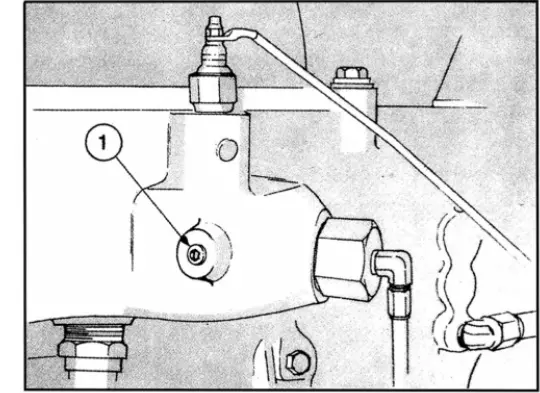
- If the engine gives no indication of starting during the first three full strokes of the preheater pump,touch-check the intake manifold for heat. If there is no heat, checkthe electrical wiring. Lf the wiring is all right remove the 1/8 inch pipe plug (1, Fig. 1-6) from the manifold near the glow plug and close the glow plug manual switch for 15 seconds and observe the glow plug through the 1/8 inch plug hole. The glow plug should be white hot; if not, connect the wiring to a 6-to 12-volt (as used) source and check the amperage; it should be 30 to 32 (minimum).If the glow plug is all right, check the manual switch and resistor (if used) and replace if necessary
Note: The preheater priming pump, switches and resistor are located at the instrument panel and are to be checked during engine starting.
The cold starting aid, approved for use in Cummins Engines, has been based upon starting aid capabilities to -25°F[-32°C].
 Caution: Do not attempt to use vapor compound type starting aids near heat open flame or on engines equipped with a glow plug system.
Manually Operated Valve
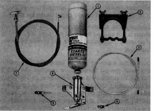
The manually operated valve illustrated in Fig.1-7 includes the valve body assembly (6), clamp (2) and nylon tube (3). The fuel cylinder (1), atomizer fitting (5) and pull control (7) must be ordered separately Standard pull or throttle control cables may be used, to actuate the manual valve, if desired.
Electrically Operated Valve
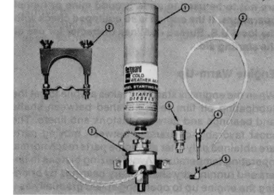
The electrically operated valve Fig.1-8 includes the valve body (7),90 degree elbow(5)clamp(2) push button switch(6),and nylon tube (3).The thermostat is mounted on the engine exhaust manifold and cuts out the valve by sensing manifold heat when the engine is running. See parts catalog for fuel cylinder (1) and fuel atomizer fittings (4).These fittings must be ordered separately as required.
Note: The operated valves are designed for V engines. Applied on K engine maybe some different.
Installation Recommendations
The atomizer fittings must be mounted in the engine air intake manifold or inlet connection to provide an equal distribution of starting fuel to each cylinder. The atomizer holes are 180 degrees apart and must be mounted so the spray is injected the long way” of the manifold. If incorrectly installed, the spray goes crosswise of the manifold.
Recommended Starting Technique Using Fleetguard Starting Aid
- Set the throttle for idle
- Disengage the driven unit or make sure gears arein neutral.
- Open the manual fuel shut-down valveor electric shut-down valvewhichever is used
- Engage the starter and while cranking,apply meteredamounts ofstarting fluid until the engine idles smoothly.
Use of Starting Fluid Without Metering Equipment
- Spray starting fluid into the air cleaner intake
while a second man cranks the engine.
Warning: Never handle starting fluid near an open flame. Never use it with a preheater or flame thrower equipment. Do not breathe the fumes. Use of too much will cause excessively high pressures and detonation, or over speed the engine.
- Starting aid fumes will be drawn into the air intake manifold and the cold engine should start without difficulty.
Warning: Fuel oil or volatile fuel cold starting aids are not to be used in underground mine or tunnel operations. If the engine is so equipped check with the local U.S. Bureau of Mines Inspector for use of the starting aid.
